
Click here or on the foto above to access its webpage, with technical details.
I got this set at the RadioActivity 2012 Flea Markeet in Beltsville, MD, on June 21st 2012. It was a real bargain once I paid only US10 for the unassembled but complete set with a not so rough cabinet. The veneer was a little bit delaminated on the front. The lateral was in a good shape, only with an old brittle finish.
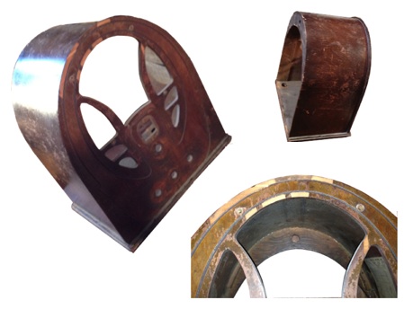
The first step was to remove the old varnish with a plastic scraper, an old toothbrush, toothpicks, and a spray gel stripper, followed by a stripping residuals wipe off with a mineral spirit embebbed rag. This removed all traces of the old cabinet finish.

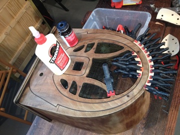
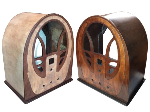
The next step was to glue the veneer with contact glue for larger pieces and wood glue for 2 tiny pieces next to the speaker screw hole. Next, I sequentially sanded with 220, 300, and 400 sand paper, and stained the darker part of the front veneer and the new veneer with Min-Wax Dark Walnut to match the surrounding wood color. After getting the desired color I used a 500 grade sand paper before the first application as well as between the other 3 layers of lacquer (spray can) used as the new finishing varnish.
The next step was to replace the torn grill cloth with a new one of the same pattern. They are very hard to find nowadays. However, fortunately, I did get some from a fellow at the RadioActiity Flea Market.


Restoring the electronics - Though not too bad, the chassis was very dirt, with a not original black cardboard covered electrolytic, with the orange dial broken, and a 200 ohms not original choke underneath the chassis. Also the output tube 42 was missing.


The first step, as usual, was to clean the chassis completely with a Dremel wire brush followed by a compressed air blow off. Also, I squirted De-Oxit contact cleaner inside all of the controls to clean and remove corrosion. Finally, I used a toothbrush and a smoke pipe strip brush with isopropyl alcohol to clean the tuning cap. Next, I painted the power transformer with black spray paint.
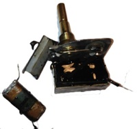
The can electrolytics were mounted in a dual clamp with a cardboard sleeve and a single screw in the middle to hold them tight. First, I replaced the black cardboard electrolytic with an old philco can electrolytic, and restored both cans taking out their innards and putting new capacitors inside them. The tone control cap was removed from inside the metal structure and replaced with a new one. The original tar was put back in place using a hot gun for melting it. The choke was replaced by a 2W resistor as suggested by Ron Ramirez at http://philcoradio.com/phorum/archive/i ... -1768.html. Thus, I did replace the out of specification 200 ohms choke with a 2W 2.2 Kohm resistor and increased the Eletrolytic Condenser #49 from 6 to 22 µF, and it worked fine. The speaker was in a great shape and I just brushed and air cleaned it.
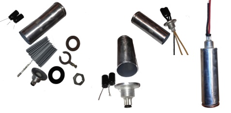


All tubular capacitors were replaced and some out of specification resistors. Each one of the the 5 Philco block condenser was reformed as I did when restoring the radio Philco 89 in March 18, 2001, as reported in this blog. Next, I replaced the broken dial with a reproduction from Radio Daze, and new rubber washers and Philco chassis screw reproductions from Renovated Radios. The power cord was replaced by a cloth covered type, like the original. The Radio is now in a great shape as you can see in the pictures below.
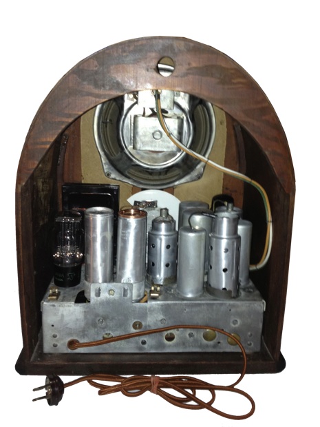
I found one mistake in the schematics and probably a not documented update since a block condenser underneath the chassis is in place of a tubular one as described by the schematics:
1) A dot is missing where the line from the primary of the 1st IF xfmr to the primary of the output xfmr crosses the line from the second 8µF electrolytic and the resistor #27. Without this connection, there is no rectified B+ to the set.
2) A block condenser 3615BM is in the circuit as #27 which is described in the schematics as being a tubular type.
